


THE METER
CUBE SERIES USER MANUAL
NOTICE
This manual describes the full version of THE METER CUBE.
The app is currently still being finalised, and some of the features described in this document may not yet be available or may differ in the version of the app you are using.
Consequently, some screenshots, procedures and descriptions in this manual may temporarily differ from the application’s actual behaviour. Any missing features will be made available in future updates.
Contents of the manual
This manual will guide you through discovering and using the CUBE3e, designed to carry out environmental measurements.
Inside you will find information on:
- The hardware components of the device
- The app THE METER CUBE and THE METER DOCTOR
- The operating modes: automatic, manual and distance meter
- The management and export of scans and projects
- The calibration procedure of the CUBE
By following the directions in this manual you will be able to achieve consistently reliable results and keep your device in optimal condition.
By consulting the table of contents, or using the search bar, you can quickly find all the information you need.
Device overview
What does your CUBE look like? Here is the list of hardware components.
Devices series CUBE3e
- Laser (visible light)
- TOF (invisible light)
- Side bubble
- Easel screw
- USB type C port
- Upper bubble / LED notifications
- Full key
- Blank key
- Reset button
- Charging LED

LED Notifications
Turning on device
To turn on the device hold down the full button until the LED light turns green.

Similarly, for power off, hold down the full button until the light turns white.

Please note 
To perform a device reset, hold down the full and empty buttons until the LED remains off for at least 10 seconds.
Connection and charging
Once the CUBE is turned on, the LED flashes green, signaling that it is waiting to connect to a mobile device. Once connected, the light turns solid green.

If in office

Battery >25%

Battery <25%
If the CUBE is charging, the LED alternates between blue and green flashes throughout the process; if the battery is below 25 percent, green signals are returned in red instead.
Scan and download
During the acquisition and download phase, the LED has a steady green light.

Laser level and calibration
In control operations, the LED has steady blue light during the execution of the laser level, while it has flashing blue light during the compass calibration test.

Battery
By clicking the full button when the device is off, you can view the charging status of your CUBE by the green blinking of the upper bubble: 1 blink between 25% and 50%, 2 blinks between 50% and 75%, 3 blinks between 75% and 99%, 4 blinks at 100%.

When the device is charging, the flashes will be returned in blue.

If the battery is less than 25%, the LED flashes red.

Connect the CUBE
- Turning on the device
Hold down the full button until the white LED turns green and starts flashing. - Apri l’app THE METER CUBE sul tuo smartphone o tablet e, dalla homepage, seleziona CERCA IL TUO CUBE
 .
.
Verifica che il Bluetooth sia attivo sul dispositivo. - Connection
The app connects to CUBE automatically. If multiple devices are detected, select the name of your CUBE from the list and tap CONNECT.
Can’t find your device?
If you don’t see your device, press UPDATE  to update the list of available devices.

Your device
Once the CUBE is connected, on the screen Home  you will see the device name, model, and battery level.


- Tap on the device illustration to access the technical details screen, from which you can rename your CUBE or disconnect it. Alternatively, you can disconnect the device by holding down the CUBE’s full button until the LED turns red.
- The button SCAN
 immediately starts a scan using the app’s default settings or, if you have already scanned, the last settings used.
Laser level
The functionality LASER LEVEL  shows the points the CUBE detects during a full rotation on itself.
It allows you to place objects, draw references, and check alignment quickly and accurately, without having to manually mark points.
Please note
Do not move the support surface or touch the CUBE until the rotation is complete.

Automatic mode
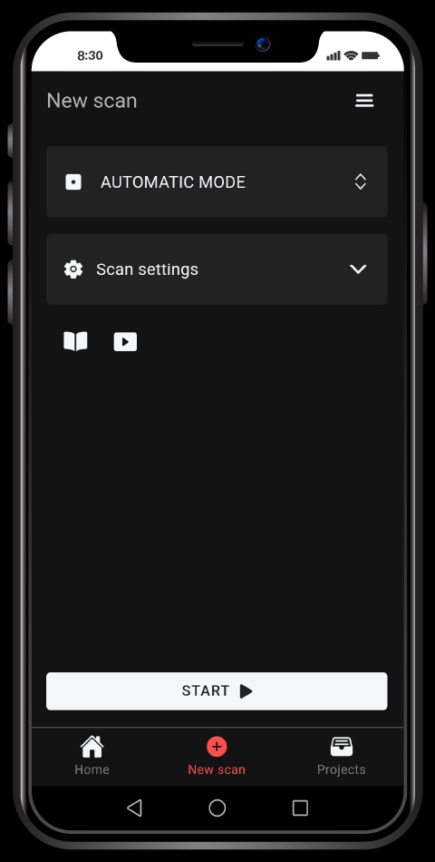
The screen New Scan  allows you to select the scan mode and customize its settings.
In automatic mode, the CUBE will survey the environment autonomously, rotating 360°.
When the scan is complete, you will see a planimetric preview in the form of a point cloud.
Single scan
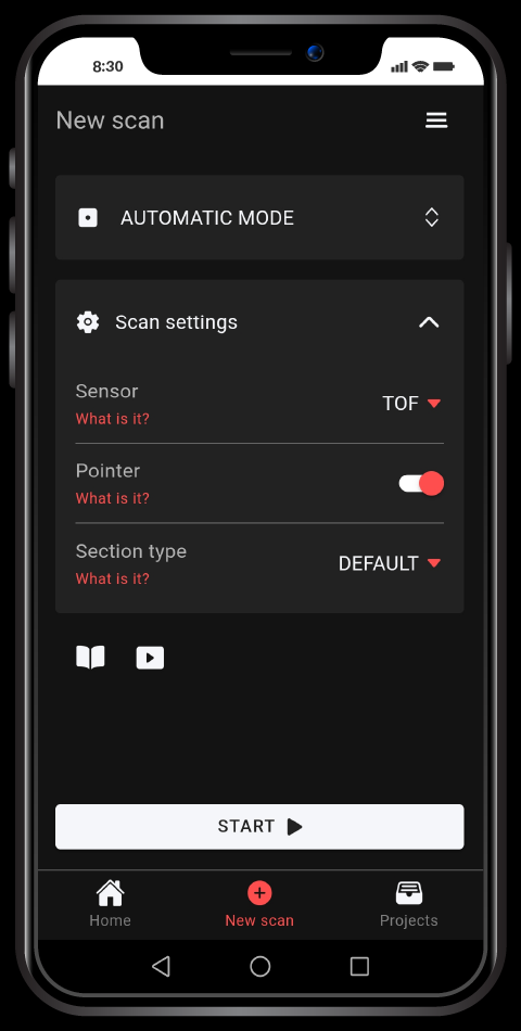
Sensor
You can choose which sensor to use for scanning:
- LASER (± 1 mm)
This is the sensor with visible red light and enables high-precision scanning.You can select the level of detail: the number associated with the Laser (1600, 640, 320, etc.) indicates how many points are detected during the scan. Higher point density increases accuracy but requires longer acquisition times. - TOF (± 2 cm)
This is the central sensor that is not visible and maximizes the acquisition speed at a lower accuracy than the Laser.
Please note
Times and accuracy vary considerably. Choose the sensor and point density based on the type of Survey you need to perform.
Pointer
You can choose whether to activate the laser pointer, using the light beam as a visual reference to locate points during the Survey.
Execution
Floor plan
After choosing the settings and making the necessary checks, tap START to start the automatic scan.
Please note
Position the CUBE by making sure it is properly level and placed in a spot that provides a full view of the space and its details.

Vertical section
With the same mode, you can also perform section surveys by rotating the orientation of the CUBE and positioning it with the side bubble facing up.
Please note
The scans are always returned in front view with respect to the central bubble. In this case, the section results reversed.

Interruption
If you stop the scan, the system still processes the points surveyed up to that point, returning a partial survey.
However, this survey cannot be used to continue with a Multiscan.
Scan preview
The scan preview shows the points detected during the acquisition in the form of a point cloud.
- In the plan, the view is oriented with North upward and the points are displayed in green.
- In the section, the view is oriented with the floor down and the dots are displayed in white.
Using the touchscreen, you can move through the Survey as you would on a photo or map, moving and zooming the view.
- The icon
 (Expand) allows you to view the preview in full screen.
 - The CUBE and the first detected point of the scan are highlighted in light blue.
- The slider
 represents the scan rotation point (pivot).

Reliability of points
The preview also shows an estimate of the reliability of the detected points, indicated by a color scale:
- Green / White → most reliable points
- Yellow
- Orange
- Red → less reliable points
Through the icon  (Customize Preview) you can customize the preview view to get a cleaner, more readable view directly in the app.
In particular, you can:
- Hide the problem areas (yellow and red)
- Temporarily hide markers and inserted photos
Tools
% points 
Allows changing the number of points displayed in preview (from 400 to 3200), to balance performance and level of detail.

Marker 
This function allows you to place markers on the floor plan to signal:
- Environments


- Points of interest or furnishings


- Technical elements


- Environments
You can also add a textual annotation and indicate any encumbrances.
After selecting a marker, it is placed in the center of the screen. Move the floor plan to place it at the desired location, then tap SAVE.

Please note
Markers and their comments are exported to the DXF file in a dedicated layer called“Marker.”
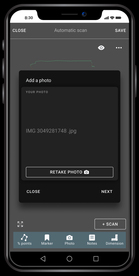
Photos 
This function allows you to add a photograph and place it on the floor plan.
For each photo you can enter a textual annotation.
Placement is done in the same way as for markers.
Please note
The photos and their comments will be placed in the .DXF file in a special layer called“Photos.”
Note 
Allows a general annotation to be added to the scan.

Dimension 
This function allows you to open a preview of the scan and freely enter dimensions directly on the floor plan.
To add an elevation, tap the dedicated icon : the Survey preview will open.
Move the plan until the first point of the elevation is positioned at the slider  , then tap + DIMENSION. Position the second point in the same way and again tap + DIMENSION : the distance between the two points is automatically displayed on the plan.
If you add a third point, a second dimension is created and the size of the angle between the two is also given.
You can:
- Remove the last point entered by tapping the appropriate icon

- Stop dimension entry by tapping the appropriate icon

Once the entry is complete, tap SAVE PDF to generate and save to your device a PDF file containing all dimensions and related dimensioned features.

Please note
Although the PDF is generated, the dimensions are not saved in the app. Once you exit the mode, you will not be able to retrieve them.
Export
Sharing the project
Through the icon  (Survey Options) you can share the project via email, messaging services or social networks.
You can choose from the following formats:
- .DXF
 → file compatible with major design software
 - .CUBE
 → RAW file used by THE METER support team for diagnostic activities and assistance in specific cases
Rescue
Via the SAVE (top right) you can save the scan, name it, and choose whether to insert it into an existing project or create a new one.
Multiscan
After making the first scan, from its preview, you can start a Multiscan via + SCAN, the function that allows you to merge several Surveys into a single .DXF file.
The function is based on overlapping points in common between the different scans.
Therefore, to obtain a correct result, it is essential to respect the positioning criteria explained below.
Step 00
Prepare the environment and don’t move the CUBE
Step 01
Mark the anchor point
Step 02
Move to the second position
Step 03
Frame the new anchor point
Step 04
Accept scan
Step 00
To continue, make sure you have not moved the CUBE after the first scan and do not move it until indicated in Step 2. If you have moved it, you must repeat the first scan respecting this criterion.
Before starting a multiscan, it is essential to carefully examine the overall environment to be scanned in order to identify the optimal path to follow, taking into account the following criteria for positioning the device for the various scans: it is necessary to ensure that at least 60% of the points are shared between the current scan and the previous one, and to position the anchor points on smooth, non-reflective and non-transparent surfaces. Also try to maintain good perpendicularity and a short distance between the instrument and the surface on which you will place the anchor point; this ensures that you fix it in the part of the scan that is richest in reliable data.
Step 01
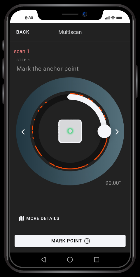
The first step is to mark an anchor point, which represents the point common to all the scans.
Use the app’s control pad to rotate the instrument head. You can use the white button for a wider rotation, or the arrow keys to make small adjustments and fine-tune the orientation to the desired position.
The red dots in the target ring indicate points that are not ideal as anchor points and correspond to noise points detected in the previous scan.
As you move the control pad’s arrow keys, the CUBE rotates in preset steps, each corresponding to 0.225°.
To make the reading clearer, the value displayed in degrees (°) is rounded to the second decimal place.
Please note
Physically mark the anchor point on the wall (for example, with a post-it note with an X on it) before continuing. This step is critical for repositioning the laser to exactly the same spot during the next scan.
Once the anchor point has been defined, tap PROCEED to save it.If you wish to repeat the point selection, tap CANCEL.
Please note
To cancel Multiscan completely, tap BACK to return to the preview of the first scan.
Step 02
Move the CUBE to the second position for the next scan.

Overlap of scanned points >60%

Anchor point on regular non-reflective or transparent surfaces

Anchor point in the most reliable scanning part
First a scan is performed from an initial position, as shown in Fig. 1.
Then the instrument is moved and a second scan is performed, as shown in Fig. 2.
However, the second scan must also include a part of the environment already surveyed in the first scan. This common part is needed for the system to figure out how to properly connect the two surveys.
Fig. 3 shows the overlap between the first and second scans. To achieve proper alignment, the common points must be greater than 60%.

Fig. 1

Fig. 2

Fig. 3

Step 03
Re-frame the anchor point marked in Step 01.
After moving the CUBE, make sure that:
- Is properly leveled (on the bubble)
- Is at the same height as the anchor point
If these conditions are not met, areas in common between scans may not match correctly.
Then proceed with the scan by tapping START .

Please note
If you stop a scan during a Multiscan, you get a partial Survey and will not be able to continue with further scans.
Step 04
If the union between the scans is satisfactory, tap ACCEPT to preview the result.
If there is an error, you can repeat the process by tapping CANCEL: you will return to Step 2 and can follow the steps described above again.

Please note
The anchor point will be the last one set.
Merge scans
Through the preview you can work on the obtained Survey as described in the Scan Preview section.The new scan is shown in green, while previous ones are shown in blue.
From here you can continue the Multiscan via the button + SCAN, adding a new scan, or proceed with saving the project.
Remember that you have to take into account all the placement criteria for each additional scan you are going to perform, since the tool only takes into account the last anchor point and the last scan performed.
This means that each new scan must be correctly linked to the one immediately preceding it. This means that if you do not cover at least 60% of the area scanned in the last scan, you will not be able to have a link between scans.

If you need to scan a nonconcurrent area you will need to create a path of intermediate scans. Each step must maintain sufficient commonalities with the previous scan and, when necessary, include the acquisition of a new anchor point.
In this way, the system can correctly link all scans together and reconstruct the Survey without losing alignment.

Manual mode
With Manual mode, you can perform Surveys by directly selecting surface points. By rotating the CUBE head, you can create polyline floor plans avoiding clutter or unwanted elements in the final DXF file.
In the section Scan type you can choose how to control the rotation of the CUBE during the Survey:
- CLASSIC: uses the interface control pad to rotate the head of the CUBE.
- ENCODER: manually rotates the head of the CUBE while keeping the base of the instrument stationary.

Manual Mode CLASSIC

Manual Mode ENCODER
Tap START to enter manual mode.
In manual mode, the red laser pointer is active.
Manual Mode CLASSIC: Rotate the CUBE head to the desired angle using the control pad, using the circular button for larger rotations and the arrow buttons to move in 0.225-degree increments. When the pointer is positioned at the desired point, tap MARK POINT. The point is immediately displayed in the preview.

Manual Mode ENCODER: Manually rotate the CUBE head.
When the pointer is positioned on the desired point, tap MARK THE POINT or use the empty button on the device. The point is immediately displayed in the preview.
Please note
In Manual Mode ENCODER, it is important not to move the CUBE until the marked point appears in the preview. Depending on the surface, this may happen immediately or take up to 3 seconds.

Nella schermata è possibile vedere l’anteprima della scansione, con la posizione del CUBE evidenziata in azzurro.
Point and segment management
Using the ”  ” button Segment Type you can choose whether to mark a single point or create segments between the detected points, assigning a specific type to each (door, window, furniture, simple segment, etc.).
- Using the icon (Delete) you can delete the last point entered.
- Through the icon
 (Clear All) you can remove all points.
These operations are also available in the full-screen preview.
Una volta nell’anteprima, portato al centro della schermata il cursore rosso sul segmento desiderato, è possibile:
- delete it (the second point of the segment is removed)
- change the type
- add an annotation
Via the icon  (Expand) you can view it in full-screen mode with the same features as those found in Anteprima della scansione.
The lower section contains the controller for rotating the CUBE’s head and selecting points.

Distance meter mode
With this mode, you can make measurements of any distance in real time, in single or sequential mode.
Type of measurement
CLASSIC: you can manually set the starting point of the measurement.
REAL-TIME: the device automatically calculates the distance in real time from your location.
Location
Depending on your measurement needs, you can set the reference point for calculating the distance from the instrument by choosing from:
- AVANTI (limite frontale)
- CENTER
- DIETRO (limite posteriore)

For more accurate measurements, rest the back of the device against a surface to reduce its movement while pressing the blank button to capture the measurement.

- Impostazione DIETRO: la distanza parte dal lato posteriore dello strumento
- Impostazione AVANTI: la distanza parte dal lato frontale dello strumento
- CENTER setting: the distance starts from the center of the instrument

Scans
In the section Projects  you can view all the project folders saved in the app, containing your scans.
From here you can:
- share an entire project via the icon (Project Options) you can share, rename or delete the project. When sharing, the project is exported as a .zipper file containing all the scans
- Open a project folder to view its scans

The project
Within each project you can add a general annotation (visible only in app) and view the list of contained scans.
Each scan is accompanied by an identifying icon indicating its type:
- simple scan

- multiscan

- section

- manual scanning

Via the (Options) icon of a scan you can:
- view technical information
- open geolocation
- share the DXF file via the device sharing system
- rename the scan
- delete the scan
Within each scan you can preview it with the same functionality described in the Scan Preview section.

Export Settings
From the menu you can access the Export Settings  .
.
Any changes to export parameters are automatically saved and applied to subsequent exports.
Smoothing Filter
Smoothing filters act on the data contained in the scans only during export by going to filter the detected points, without changing the original data, to eliminate possible background noise.
Selecting Raw the original data are exported.
Ultrasoft, Soft, Medium e Hard reprocess the data with increasing “intensities.”

Please note
Depending on the Smoothing Filter used, some scanned details, for example edges or tiles that already in the Medium are very smooth.
Export layers
In Export Layers you decide which layers to have in the DXF resulting from exporting the scans made with your CUBE, without going to change the original data.
- Laser points / TOF: The exported points are exactly those detected by the scan according to the Smoothing Filter enabled.
- Simplify Soft/ Medium/ Hard: export a simplified representation of the survey in which the acquired points are converted to a polyline, in this case with a low, medium and high degree of simplification respectively
- SimplifiedExport: is ideal for exporting DXFs compatible with the most widely used 3D drawing software.

Please note
The only export format compatible with Simplified Export is the DXF Classic (see export format).
Export format
The export format setting allows you to make your photo documentation compatible depending on the CAD software you use, since not all CAD programs handle image insertion. There are three settings: Classic, Classic + Images, NextGen.

- Classic: exports a “classic” DXF file, without including any photos in the survey.
Similarly, sharing an entire project generates a .zipper file containing all surveys in DXF format, without images.
- Classic +Pictures: exports the scans and photos into a single .zipper file.
If you have added pictures, you will find a “classic” DXF file and all the photos in JPEG format in the ZIP.
In the DXF, there are camera-shaped markers; each is associated with a label that shows the name of the corresponding JPEG file.

- NextGen: exports the surveys in DXF format including, within the CAD software, any photos associated with the floor plan (as shown in the image).
If photos are present, the export generates a .zipper file containing the DXF file with image references and all photos in JPEG format.

Device configuration
Calibration
CUBE calibration allows you to set North correctly, ensuring an accurate and reliable reference for your measurements.
During the procedure, the device performs a test to check the compass calibration by rotating the head 360° in 4 steps.
The process is accompanied by the LED signal:
- steady blue during movement
- blue flashing between steps

Support
In this section you will find frequently asked questions (FAQs).
If you do not find the answer you are looking for, you can contact our technical team by sending a support request.
Just enter your contact information and describe the problem you are experiencing.

Guides
In this section you will find links to useful technical multimedia content to support you as you perform the Survey.
You can also access the same content in the Tutorial section of the site.

Updates and maintenance
To update and keep your THE METER device efficient, download the THE METER DOCTOR app.
With THE METER DOCTOR you can:
- install firmware updates
- Solve any problems quickly and with guidance
Keep your device up-to-date to ensure optimal performance.
